Serie ML
Programmable DC Power Supply
- Size
- Power
- 500 kW to 10 MW+
- Manufactured
- USA
- Build-time
- 10-12 weeks
La Serie ML di Magna-Power Electronics è stata progettata da zero per stabilire un nuovo standard in densità di potenza e prestazioni. Sfruttando la tecnologia avanzata di raffreddamento ad acqua, i modelli della Serie ML da 500 kW e 1.000 kW raggiungono un aumento della densità di potenza quasi quadruplicato rispetto ai modelli raffreddati ad aria di Magna-Power. Con la possibilità di collegarsi in configurazioni parallele master-slave, la Serie ML può raggiungere livelli di potenza superiori a 10 MW. Basati sull'affidabile topologia di elaborazione della potenza alimentata a corrente di Magna-Power e sulla tecnologia innovativa di neutralizzazione armonica, gli alimentatori della Serie ML offrono una conversione di potenza affidabile ed efficiente con bassa distorsione armonica. Progettati e fabbricati a Flemington, New Jersey, gli alimentatori della Serie ML incarnano l'impegno di Magna-Power per la qualità, l'affidabilità e l'ingegneria avanzata.
Caratteristiche principali
- Modelli da 500 kW e 1.000 kW; espandibile fino a 10 MW
- Controllo di precisione a 12 bit
- Programmazione remota tramite comandi SCPI
- Funzioni di protezione programmabili
- Blocco di sicurezza per arresto di emergenza esterno
- Driver LabVIEW
- Funzionamento continuo a piena potenza fino a 50°C di temperatura ambiente
- Porta utente I/O analogico-digitale a 37 pin
- Solenoide integrato per il controllo della condensa
- Master-slave ad alte prestazioni
- Rilevamento della tensione locale, remoto e senza piombo
- Opzioni di comunicazione standard RS232 e LAN TCP/IP Ethernet disponibili
- Piattaforma software RIS Panel inclusa
- Prodotto negli Stati Uniti

Talk with an expert


High power density, water cooled megawatt-scale DC power systems
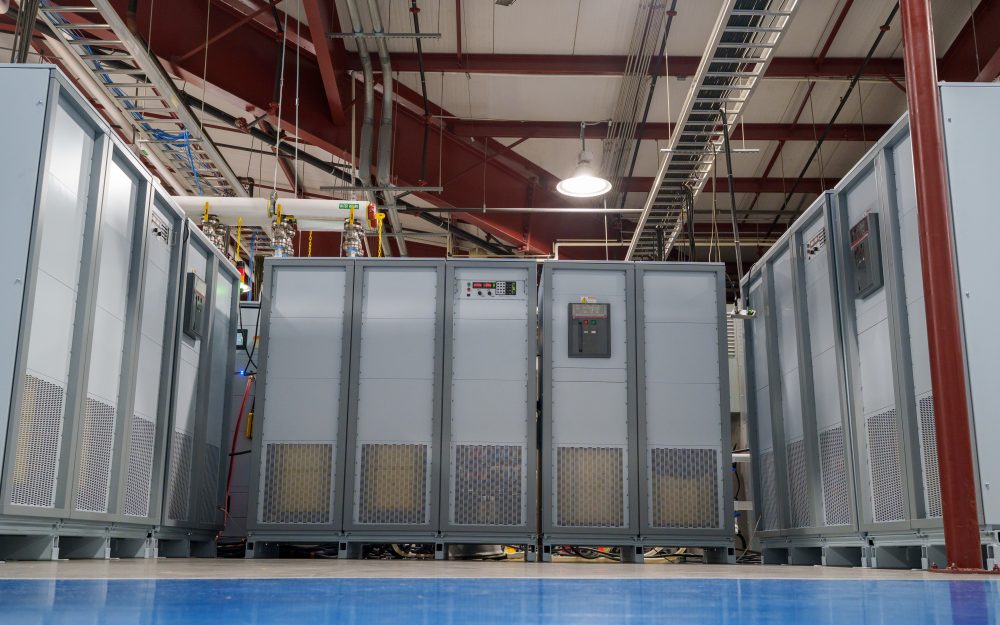
High-density, water-cooled performance
Clean, precise output from 500 kW to 10 MW+.
The ML Series programmable DC power supplies leverage advanced water-cooled chill plates and internal manifolds to deliver 500 kW and 1,000 kW per cabinet at up to 96% efficiency, achieving nearly fourfold higher power density than comparable air-cooled models while running at full rated power to 50°C ambient. Built on MagnaDC’s current-fed topology, the ML Series provide 12-bit (0.025%) programming resolution, tight line/load regulation, and ±0.075% voltage and current programming accuracy with low ripple—bringing lab-grade performance to multi-megawatt test and process systems.

Stepless front-panel control with blank panel option
Hands-on where you want it, hidden where you don’t.
The standard SL front panel provides rotary and key-based control, bright digital metering, and clear status indicators, so operators can configure setpoints, start and stop the supply, and see system health at a glance. For OEMs and production tools, the optional blank (C-version) front panel removes local controls altogether while retaining full control via communication interfaces and rear 37-pin user I/O, keeping systems secure, clean, and operator-proof.
Configured-to-order with integrated options
Rich standard features, extended when needed.
Like the rest of the MagnaDC line, MT Series supplies start with a strong control base: SCPI over RS232, isolated rear User I/O, LabVIEW and IVI drivers, and Remote Interface Software included. From there, integrated options let you tailor each system for its role—High Isolation Output (+ISO) for extended series stacking, High Slew Rate Output (+HS) for faster dynamics, LXI TCP/IP Ethernet (+LXI) and IEEE-488 GPIB (+GPIB) for additional communications, plus protection and mechanical options such as an Integrated Blocking Diode (+BD) and Pedestal Base (+PB) for fixed installations.
Harmonic Neutralizers for cleaner high-power systems
Reduce THD at the source for easier power-quality compliance.
Input current harmonics are an inherent by-product of three-phase rectifiers: a standard 6-pulse front end produces harmonic currents at 1, 5, 7, 11, 13… times the fundamental, with the 5th and 7th components alone at roughly 20% and 14% of the fundamental. These currents can excite sensitive loads—such as lighting ballasts with series capacitors/inductors—and make meeting power-quality guidelines like IEEE 519 more challenging. The most reliable way to minimize harmonic issues is to eliminate harmonic current at the source.
For high-power systems, Magna-Power manufactures specially wound Harmonic Neutralizers that multiply the number of input phases and dramatically cut input current THD, passively. Standard 1.5–150 kW Magna-Power supplies draw a 6-pulse waveform, while 250 kW MT Series and 500 kW ML Series models embed a 12-pulse Harmonic Neutralizer and 1000 kW ML Series models embed a 24-pulse Harmonic Neutralizer—transparent to the user.

Rugged by design: safety + reliability, as you'd expect from Magna-Power.

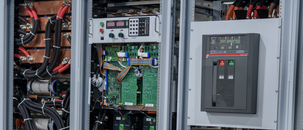
Reliable current-fed power processing
Rugged by design: self-protecting topology for uptime.
The SLx Series uses a high-frequency, current-fed architecture that adds a control stage beyond conventional voltage-fed designs. This topology inherently limits fault energy—avoiding fast-rising current spikes and magnetic core saturation so the supply self-protects and your load stays safe. Paired with state-of-the-art SiC power semiconductors, SLx delivers class-leading power density, efficiency, and reliability, including continuous full-power operation up to 50°C ambient.
- Current-fed architecture with an added control stage vs. voltage-fed.
- Inherent surge immunity—no current spikes or core saturation.
- Self-protecting behavior under fault conditions.
- SiC devices for high density and efficiency; full power to 50°C.
Safety features & interlock
Soft-start, programmable protection, and a mechanical line disconnect for true safety.
MagnaDC supplies start gently and watch continuously. A soft-start stage keeps inrush below steady-state draw, while built-in diagnostics monitor line, thermal, and control conditions. In standby or on a diagnostic fault, an embedded AC contactor mechanically disconnects the mains, assuring the unit only processes power when intended. Faults are shown on the front-panel status display, through 5V digital outputs, and are queryable via SCPI.
-
Programmable trips: Over voltage (OVT) and over current (OCT)/
-
Control integrity: Program-line over-voltage detection.
-
Thermal protection: Over temperature on internal heatsinks.
-
Interlock/E-stop fault monitoring as a standard diagnostic.
-
Field integration: 5V interlock input (with 5V reference) for a dry-contact, latching inhibit with control power maintained.
From lab scripts to factory PLCs, flexible programming & integration.
Software integration made easy
Readable commands, quick results—works with any language.
MagnaDC power supplies exposes a clear, text-based API with native SCPI, an ASCII-based command language sent over socket communications. Over 40 well-documented commands cover start/stop, set points for voltage, current, high-accuracy measurements, and full configuration—so your scripts and systems go from proof-of-concept to production fast.
- SCPI command sets with consistent behavior.
- Start/stop & protections: enable output, set trip limits, query status.
- High-accuracy reads: voltage, current, power, and sense feedback.
- Developer-driven documentation & examples.
import serial
magnaPower = serial.Serial(port='COM4', baudrate=19200)
magnaPower.write('*IDN?\n'.encode())
print magna_power.readline()
magnaPower.write('VOLT 0\n'.encode())
magnaPower.write('CURR 0\n'.encode())
magnaPower.write('OUTP:START\n'.encode())
magnaPower.write('VOLT 270\n'.encode())
currSetPoints = [50, 100, 150, 250]
for currSetPoint in currSetPoints:
    print 'Setting Current to %s A' % currSetPoint
    magnaPower.write('CURR {0}\n'.format(currSetPoint).encode())
    magnaPower.write('MEAS:VOLT?\n'.encode())
    print magnaPower.readline()
    time.sleep(20)
magnaPower.write('OUTP:STOP\n'.encode())
magnaPower.close()
magna_power = serial('COM4', 'BaudRate', 19200);
fopen(magnaPower);
fprintf(magnaPower,'*IDN?');
idn = fscanf(magnaPower);
fprintf(magnaPower,'VOLT 0');
fprintf(magnaPower,'CURR 0');
fprintf(magnaPower,'OUTP:START');
fprintf(magnaPower,'VOLT 270');
for currSetPoint in [50, 100, 150, 250]
    display('Setting Current to '+currSetPoint+' A');
    fprintf(magnaPower, 'CURR '+currSetPoint);
    fprintf(magnaPower,'MEAS:VOLT?');
    display(fscanf(magnaPower));
    pause(20);
end
#include <stdio.h>
#include <stdint.h>
#include <string.h>
#include <windows.h>

int main()
{
    printf("Opening connection.\n");

    uint8_t recvBuffer[sizeof(uint8_t) * 256];
    memset(recvBuffer, 0, 256);

    // Choose the serial port name.
    // COM ports higher than COM9 need the \\.\ prefix, which is written as
    // "\\\\.\\" in C because we need to escape the backslashes.
    const char* device = "\\\\.\\COM4";

    // Choose the baud rate (bits per second).
    uint32_t baud_rate = 19200;

    HANDLE port = open_serial_port(device, baud_rate);
    if (port == INVALID_HANDLE_VALUE) { return 1; }

    char* scpiCmd = (char*)"*IDN?\n";
    size_t cmdLen = strlen(scpiCmd);
    int result = write_port(port, (uint8_t*)scpiCmd, cmdLen);
    if (result < 0)
        return -1;

    result = read_port(port, recvBuffer, 256);
    printf("Sent: %s\nReceived: %s\n", scpiCmd, recvBuffer);

    scpiCmd = (char*)"VOLT 0\n";
    cmdLen = strlen(scpiCmd);
    result = write_port(port, (uint8_t*)scpiCmd, cmdLen);
    if (result < 0)
        return -1;

    scpiCmd = (char*)"CURR 0\n";
    cmdLen = strlen(scpiCmd);
    result = write_port(port, (uint8_t*)scpiCmd, cmdLen);
    if (result < 0)
        return -1;

    scpiCmd = (char*)"OUTP:START\n";
    cmdLen = strlen(scpiCmd);
    result = write_port(port, (uint8_t*)scpiCmd, cmdLen);
    if (result < 0)
        return -1;

    scpiCmd = (char*)"VOLT 270\n";
    cmdLen = strlen(scpiCmd);
    result = write_port(port, (uint8_t*)scpiCmd, cmdLen);
    if (result < 0)
        return -1;

    char setPoints[4][5] = {"50", "100", "150", "200"};
    char setPointBuffer[40];
    scpiCmd = (char*)"MEAS:VOLT?\n";

    for (int i = 0; i < 4; i++)
    {
        sprintf(setPointBuffer, "CURR %s\n", setPoints[i]);
        printf("Setting current to %s A\n", setPoints[i]);
        cmdLen = strlen(setPointBuffer);
        result = write_port(port, (uint8_t*)setPointBuffer, cmdLen);
        if (result < 0)
            return -1;
        memset(recvBuffer, 0, 256);
        result = read_port(port, recvBuffer, 256);
        printf("Received: %s\n", recvBuffer);
        Sleep(20000);  // 20000ms = 20s
    }

    scpiCmd = (char*)"OUTP:STOP\n";
    cmdLen = strlen(scpiCmd);
    result = write_port(port, (uint8_t*)scpiCmd, cmdLen);
    if (result < 0)
        return -1;

    CloseHandle(port);

    printf("Connection closed.\n");
    return 0;
}
using System;
using System.IO.Ports;
using System.Threading;

namespace SerialCommunicationInCSharp
{
  public class Program
  {
    static bool _continue;
    static SerialPort serialPort;

    public static void Main(string[] args)
    {
      Thread readThread = new Thread(Read);

      Console.WriteLine("Opening connection.");

      // Create a new SerialPort object with default settings.
      serialPort = new SerialPort("COM4", 19200, Parity.None, 8, StopBits.One);

      // Set the read/write timeouts
      serialPort.ReadTimeout = 500;
      serialPort.WriteTimeout = 500;

      serialPort.Open();
      _continue = true;
      readThread.Start();

      Console.WriteLine("Sending: *IDN?");
      serialPort.WriteLine("*IDN?");

      serialPort.WriteLine("VOLT 0");
      serialPort.WriteLine("CURR 0");
      serialPort.WriteLine("OUTP:START");
      serialPort.WriteLine("VOLT 270");

      string[] currSetPoints = { "50", "100", "150", "250" };
ß
      for(int i = 0; i < currSetPoints.Length; i++)
      {
        serialPort.WriteLine(String.Format("'CURR {0}", currSetPoints[i]));
        serialPort.WriteLine("MEAS:VOLT?");
        Thread.Sleep(20000);
      }

      serialPort.WriteLine("OUTP:STOP");

      Console.WriteLine("Closing connection.");
      _continue = false;
      serialPort.Close();
      }

    public static void Read()
    {
      while (_continue)
      {
        try
        {
          string message = serialPort.ReadLine();
          Console.WriteLine("Received: " + message);
        }
        catch (TimeoutException) { }
      }
    }
  }
}

External User I/O for PLC control or PHIL simulation
Wire it like an I/O module—no extra isolation needed.
Via the included rear 37-pin User I/O connector, MagnaDC supplies can be fully driven and monitored by external signals or a PLC. Voltage, current, OVT, and OCT set points are programmed with 0–10 V analog inputs, while each diagnostic condition has its own +5V digital status pin. Built-in +2.5V, +5V, and +10V reference rails let you use dry contacts without adding external supplies. All I/O is isolated from the output and referenced to earth ground as standard.
-
0–10 V analog programming for V, I, OVT, and OCT.
-
Per-fault digital outputs: each diagnostic has its own +5V pin.
-
Isolated user I/O referenced to earth ground—no extra isolators.
-
With High Slew Rate Output (+HS), high-bandwidth response and fast rise times support HIL/PHIL simulation applications.
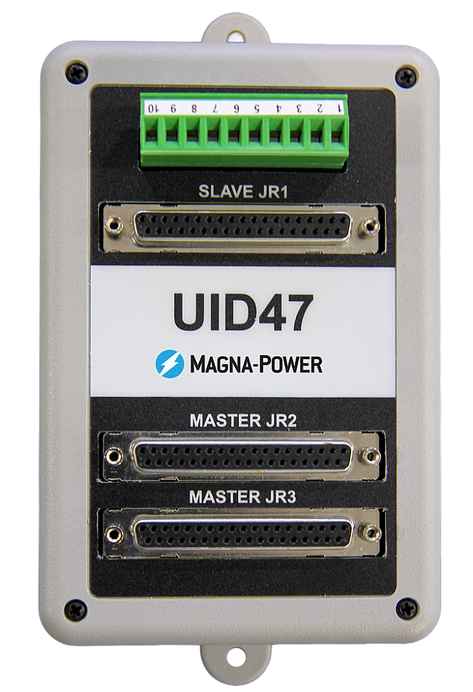
High-performance master-slave operation
Scale voltage or current without sacrificing performance.
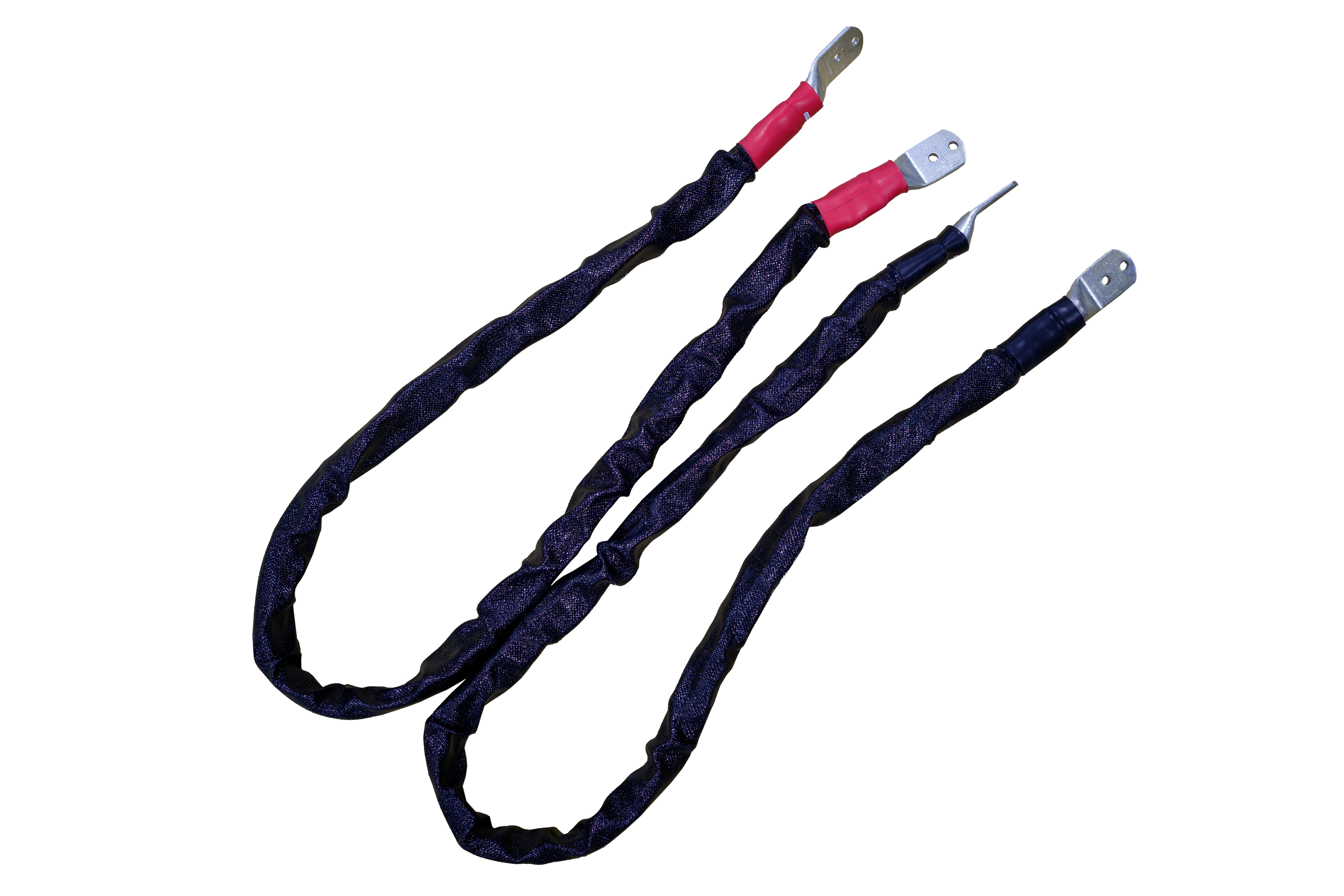
All MagnaDC supplies support master-slave operation, using gate-drive signals from the master when configured for parallel, so the whole stack behaves like a single supply—with one control loop and no noisy long analog references. The optional UID47 accessory simplifies wiring for series or parallel sets with near-equal sharing.
-
Single control loop parallel operation: Master gate-drive to slaves for consistent dynamics.
-
Plug & play with the UID47, enabling parallel or series stacks with current/voltage sharing.
-
Series up to the DC isolation rating without added hardware.
No additional ORing diodes required for parallel operation.
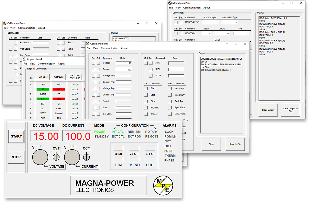
Magna-Power software, LabVIEW & IVI drivers
From virtual front panel to full automation—out of the box.
Every MagnaDC supply includes an IVI driver and NI LabVIEW driver with a full set of VIs, plus example programs so you can get talking to the hardware in minutes. For direct front-panel-style control from a PC, Magna-Power’s Remote Interface Software provides a rich view into the supply—from commands and registers to calibration and firmware.
-
IVI & NI LabVIEW drivers included with full VI set.
-
Example programs to jump-start integration and testing.
-
Remote Interface Software with:
-
Virtual front panel for manual control
-
Command panel to explore and send commands
-
Register panel for live status monitoring
-
Calibration panel for internal digital potentiometers
-
Firmware panel for in-place upgrades
-
Modulation panel to emulate non-linear profiles
-
-
All communication interfaces supported across software and drivers for a consistent programming experience.
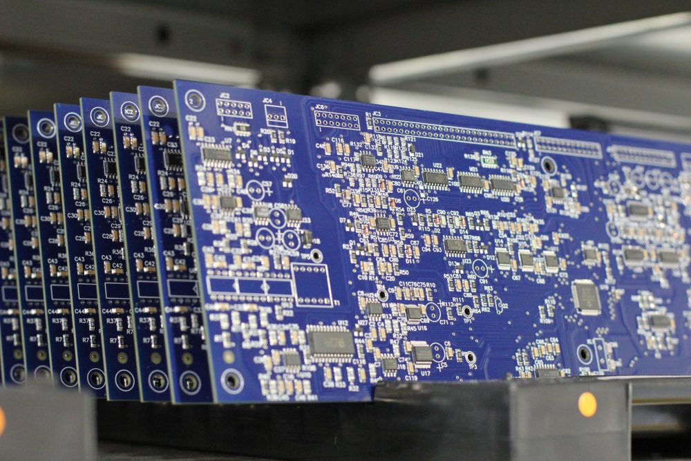
State-of-the-art USA manufacturing with worldwide support

Made in the USA
Vertically integrated manufacturing for full quality control.
Magna-Power products are designed, built, tested, and serviced at Magna-Power’s 73,500 sq-ft headquarters in Flemington, New Jersey, where metalwork, magnetics, PCB assembly, and burn-in are all done in-house for tight control over quality, cost, and lead-time.
- USA-built: Engineering, manufacturing, and service under one roof.
- In-house production: Metalwork, magnetics, SMT PCBs, and finishes.
- Proven reliability: Every unit fully tested, calibrated, and burned in.
Worldwide service & OEM parts support
Factory expertise, local response.
Magna-Power backs its products with factory and authorized service centers across North America, Europe, the UK, Asia-Pacific, East Asia, and South America—using factory procedures and genuine parts to restore units to original specifications, in or out of warranty.
- Global coverage: HQ in New Jersey plus regional authorized service centers.
- Consistent repairs: Factory diagnostics, work instructions, and system diagrams.
- Genuine OEM parts: Tested replacement assemblies for predictable, low-downtime service.
Model Ordering Guide
For both ordering and production, Serie ML models are uniquely defined by several key characteristics, as defined by the following diagram:

Serie ML Models
There are 38 different models in the Serie ML spanning power levels: 500 kW and 1000 kW. To determine the appropriate model:
- Select the desired Max Voltage (Vdc) from the left-most column.
- Select the desired Max Current (Adc) from the same row that contains your desired Max Voltage.
- Construct your model number according to the model ordering guide.
| Max Voltage Vdc |
500 kW | 1000 kW | Ripple mVrms |
Efficiency |
|---|---|---|---|---|
| Max Current Adc | ||||
| 100 | 5000 | — | 100 | 91% |
| 125 | 4000 | — | 100 | 91% |
| 160 | 3125 | — | 120 | 92% |
| 200 | 2500 | 5000 | 125 | 92% |
| 250 | 2000 | 4000 | 130 | 92% |
| 300 | 1666 | 3333 | 160 | 93% |
| 375 | 1333 | 2666 | 170 | 93% |
| 400 | 1250 | 2500 | 180 | 95% |
| 500 | 1000 | 2000 | 220 | 95% |
| 600 | 833 | 1666 | 300 | 95% |
| 800 | 625 | 1250 | 400 | 96% |
| 1000 | 500 | 1000 | 500 | 96% |
| 1250 | 400 | 800 | 500 | 96% |
| 1600 | 312 | 625 | 600 | 96% |
| 2000 | 250 | 500 | 800 | 96% |
| 2500 | 200 | 400 | 900 | 96% |
| 3000 | 166 | 333 | 1000 | 96% |
| 4000 | 125 | 250 | 1100 | 96% |
| 5000 | 100 | 200 | 1500 | 96% |
| 6000 | 83 | 166.6 | 2000 | 96% |
Specifications are subject to change without notice. Unless otherwise noted, all specifications measured at the product's maximum ratings.
AC Input Specifications
480 Vac, 3-phase
DC Output Specifications
Current control: ± 0.03% of rated current
Current control: ± 0.06% of rated current
Current control: 0.06%/ºC of rated current
< 200 ms, output current change from 0 to 63%
< 10 ms, output current change from 0 to 63%
Programming Specifications
Current: ± 0.075% of rated current
Current: ± 0.20% of rated current
Over Current: 10% to 110% of rated current
Analog programming impedance: 10 kΩ
Analog measurement outputs: 0-10V, 5 mA capacity
Analog measurement impedance: 100 Ω
Analog reference signal: 10 V, 5 mA capacity, 1 Ω
Digital control inputs impedance: 10 kΩ
Digital monitoring outputs: 5 V, 5 mA capacity
Digital reference signal: 5 V, 25 mA capacity
Interace Specifications
Referenced to ground; isolated from the DC output
See User Manual for pin layout
Physical Specifications
76.4” H x 48” W x 31.5” D (194.1 x 121.9 x 80.0 cm)
2500 lbs (1134 kg) 500 kW Harmonic Neutralizer
76.4” H x 24” W x 31.5” D (194.1 x 61.0 x 80.0 cm)
1500 lbs (680 kg)
76.4” H x 72” W x 31.5” D (194.1 x 182.9 x 80.0 cm)
3750 lbs (1701 kg) 1000 kW Harmonic Neutralizer
76.4” H x 48” W x 31.5” D (194.1 x 121.9 x 80.0 cm)
2850 lbs (1293 kg)
Environmental Specifications
Maximum inlet pressure: 80 psi
Inlet and outlet fittings provided: 1” Female NPT
Materials in coolant path: Copper pipe, PEX tubing, brass solenoid & fittings
Regulatory Specifications
CISPR 22 / EN 55022 Class A
The following are vectorized diagrams for the Serie ML. Refer to the Downloads section for downloadable drawings.


Integrated Options
Standard integrated options are available for Magna-Power products, allowing the product's performance and communication interfaces to be tailors to the specific application.
- Option
- +ISO
- Option
- +HS
- Option
- +GPIB

Accessories
External accessories and integration services available for this product.